Graphics Programs Reference
In-Depth Information
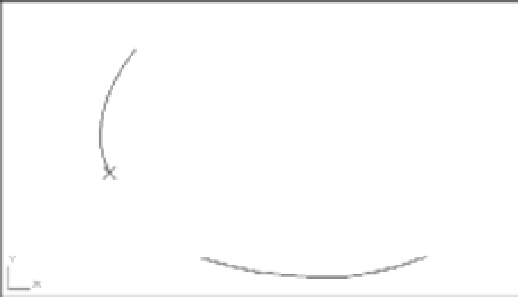
FIGURE 17.10
How the Break
option works
Place the X on the
beginning of the
break; then start
the Break option.
Move the X to the end of
the break; then type
G
↵.
You can also use the Break and Trim tools on the Tool Sets palette to break a polyline any-
where, as you did when you drew the toilet seat in Chapter 3, “Setting Up and Using AutoCAD's
Drafting Tools.”
The Insert Option
Next try the Insert option, which inserts a new vertex:
1.
Type
X
↵ to exit the Edit Vertex option temporarily. Then type
U
↵ to undo the break.
2.
Type
E
↵ to return to the Edit Vertex option.
3.
Press ↵ to advance the X marker to the next point.
4.
Enter
I
↵ to select the Insert option.
5.
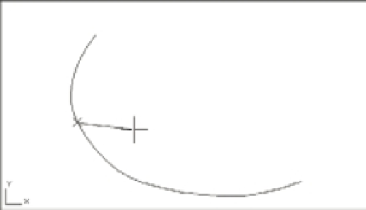
When the prompt Specify location for new vertex: appears, along with a rubber-
banding line originating from the current X position (Figure 17.11), pick a point indicating
the new vertex location. The polyline is redrawn with the new vertex.
FIGURE 17.11
The new vertex
location
Current vertex location
Rubber-banding line
New vertex location