Graphics Programs Reference
In-Depth Information
Connecting Objects with Geometric Constraints
You'll start your exploration of parametric drawing by adding geometric constraints to an exist-
ing drawing and testing the behavior of the drawing with the constraints in place. Geometric
constraints let you assign constrained behaviors to objects to limit their range of motion.
Limiting motion to improve editing efficiency may seem counterintuitive, but once you've seen
these tools in action, you'll see their benefits.
Using Autoconstrain to Automatically Add Constraints
Start by opening a sample drawing and adding a few geometric constraints. The sample draw-
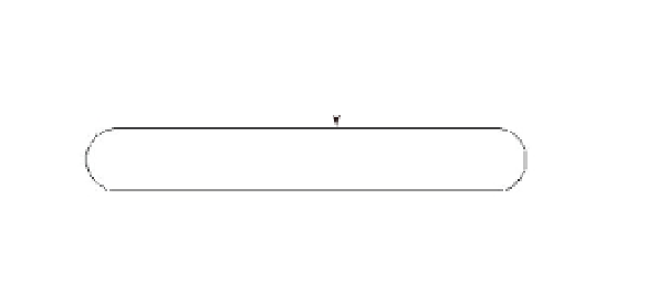
ing is composed of two parallel lines connected by two arcs, as shown in Figure 16.3. These are
just lines and arcs and are not polylines.
1.
Open the Parametric01.dwg file, which can be obtained from the companion website,
www.sybex.com/go/masteringautocadmac (Figure 16.3).
FIGURE 16.3
The Parametric01
.dwg file containing
simple lines and arcs
Lines
Arc
Arc
2.
Click the Auto Constrain tool from the Tool Sets palette, or type
AUTOCONSTRAIN
↵.
3.
Select all of the objects in the drawing, and press ↵.
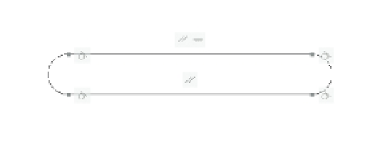
You've just used the Autoconstrain command to add geometric constraints to all of the
objects in the drawing. You can see a set of icons that indicate the constraints that have been
applied to the objects (see Figure 16.4). The Autoconstrain command makes a “best guess” at
applying constraints.
FIGURE 16.4
The drawing with
geometric con-
straints added
Parallel
Horizontal
Tangent
Tangent