Graphics Programs Reference
In-Depth Information
can use this feature to set up multiple drawing sheets based on a single AutoCAD drawing fi le.
For example, suppose a client requires full sets of plans in both
1
⁄
8
˝ = 1´ scale and
1
⁄
16
˝ = 1˝ scale.
You can set up two layouts, each with a different paper size and viewport scale.
You can also set up different Paper Space layouts for the different types of drawings. A single
drawing can contain the data for mechanical layout, equipment and furnishing, fl oor plans, and
refl ected ceiling plans. Although a project can require a fi le for each fl oor plan, a single fi le with
multiple layout views can serve the same purpose.
To create new layout views, do the following:
1.
Click the Show Drawings & Layouts tool in the status bar. The QuickView dialog box
opens.
2.
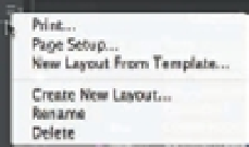
Click the menu on the upper right-hand corner of the QuickView dialog box to dis-
play the Layout options (see Figure 15.13). You can also right-click a thumbnail in the
QuickView dialog box to display the options. Choose Create New Layout. The Create
Layout dialog box appears with a default layout name (Layout2) for the new layout.
FIGURE 15.13
The Layout options
3.
Click the Confi rm button to add the new Layout2.
4.
Double-click Layout2. The new layout appears with a single default viewport.
You've just seen how you can create a new layout using the Show Drawings & Layouts tool.
The Show Drawings & Layouts shortcut menu also includes the New Layout From Template
option. The New Layout From Template option lets you create a Paper Space layout based on
a layout saved in a drawing (DWG), drawing template (DWT), or DXF fi le. AutoCAD provides
several drawing templates with standard layouts that include title blocks based on common
sheet sizes.
To move a tab, simply click and drag it to where you want it to appear. Finally, if you want to
duplicate, delete, or rename a layout, click the Show Drawings & Layouts tool and then right-
click the layout you want to edit. You can then select the option from the shortcut menu that
appears. If you select Delete, you'll see a warning message telling you that AutoCAD will per-
manently delete the layout you have chosen to delete. Click OK to confi rm your deletion.
Creating Odd-Shaped Viewports
In many situations, a rectangular viewport doesn't provide a view appropriate for what you
want to accomplish. For example, you might want to isolate part of a fl oor plan that is L-shaped
or circular. You can create viewports for virtually any shape you need. You can grip edit a typi-
cal rectangular viewport to change its shape into a trapezoid or other irregular four-sided poly-
gon. You can also use the Polygonal Viewport tool to create more complex viewport shapes, as
the following exercise demonstrates.