Graphics Programs Reference
In-Depth Information
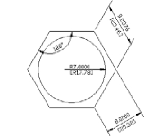
FIGURE 11.29
The jogged dimen-
sion in the drawing
Skewing Dimension Lines
At times, you may need to force the extension lines to take on an angle other than 90° to the
dimension line. This is a common requirement of isometric drawings, in which most lines are
at 30° or 60° angles instead of 90°. To facilitate non-orthogonal dimensions like these, AutoCAD
offers the Oblique option:
1.
Choose Dimension
Oblique from the menu bar, or type
DED
↵
O
↵.
2.
At the Select objects: prompt, pick the aligned dimension in the upper-right portion
of the drawing, and press ↵ to confirm your selection.
3.
At the Enter obliquing angle (press ENTER for none): prompt, enter
60
↵ for 60°.
The dimension will skew so that the extension lines are at 60° (Figure 11.30).
FIGURE 11.30
The extension lines
at 60°
Adding a Note with a Leader Arrow
One type of dimension is something like a text-dimension hybrid. The Multileader tool lets you
add a text note combined with an arrow that points to an object in your drawing. Multileaders
are easy to use and offer the same text-formatting tools as the Mtext tool. Try the following exer-
cise to get familiar with multileaders:
1.
Click the Multileader tool in the Tool Sets palette (see Figure 11.31), select Dimension
Multileader on the menu bar, or enter
MLD
↵.
FIGURE 11.31
The Leaders panel
Multileader
Add Leader
Align Leaders
Remove Leader
Collect Leaders