Graphics Programs Reference
In-Depth Information
2.
Click the Hatch tool in the Tool Sets palette.
3.
In the Hatch And Gradient dialog box, change the Type from User Defined to Predefined.
4.
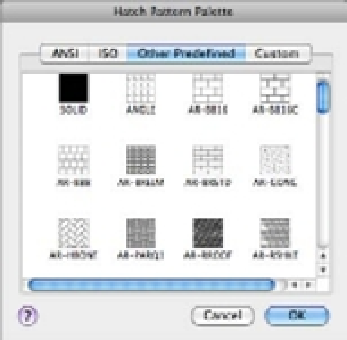
Select the ellipsis button next to Pattern, and the Hatch Pattern Palette appears
(Figure 7.8). This list has a scroll bar to the right that lets you view additional patterns.
5.
Scroll down the list and locate and select AR-PARQ1 (Figure 7.8).
FIGURE 7.8
The Hatch Pattern
Palette
6.
Click OK to dismiss the Hatch Pattern Palette.
7.
Click the Add: Pick Points button and then click inside the rectangle you just drew.
8.
Press ↵ twice to exit the Hatch command.
The predefined patterns with the
AR
prefix are architectural patterns that are drawn to full
scale. In general, you should leave their Scale setting at 1. You can adjust the scale after you place
the hatch pattern by using the Properties Inspector palette, as described later in this chapter.
ADDING SOLID FILLS
With Type set to Predefined, you can select Solid from the Pattern pop-up menu in the Hatch And
Gradient dialog box. The Hatch Color pop-up menu lets you set the color of your solid fill.
Positioning Hatch Patterns Accurately
In the previous hatch pattern exercise, you may have noticed that the hatch pattern fit neatly into
the 8´
×
3´ rectangle. The AR-PARQ1 pattern is made up of 1´ squares so they will fit exactly in an
area that is of even 1´ increments. In addition, AutoCAD places the origin of the pattern in the
bottom-left corner of the area being filled by default.
You won't always have a hatch pattern fit so easily in an area. If you've ever laid tile in a bath-
room, for example, you know that you have to carefully select the starting point for your tiles to