Graphics Programs Reference
In-Depth Information
9.
At the Erase Source Objects? [Yes/No] <N>: prompt, press ↵. You'll get a 5˝ wall
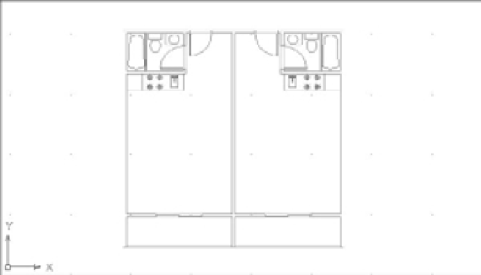
thickness between two studio units. Your drawing should be similar to Figure 7.1.
FIGURE 7.1
The unit plan
mirrored
Select this corner for the
Mirror command in step 6.
You now have a mirror-image copy of the original plan in the exact location required for the
overall plan. Next, make some additional copies for the opposite side of the building:
1.
Press ↵ to reissue the Mirror command and select both units.
2.
Use the From osnap option again, and using the Endpoint osnap, select the same corner
you selected in step 6 of the preceding set of steps.
3.
Enter
@24<90
to start a mirror axis 24˝ directly above the selected point. Metric users
should enter
@61<90
.
4.
With Ortho mode on, select a point so that the mirror axis is exactly horizontal.
5.
At the Erase source objects? [Yes/No] <N>: prompt, press ↵ to keep the two unit
plans you selected in step 1 and complete the mirror operation.
With the tools you've learned about so far, you've quickly and accurately set up a fairly good
portion of the floor plan. Continue with the next few steps to “rough in” the main components
of the floor:
1.
Click the Zoom button from the status bar and then type
E
↵, or type
Z
↵
E
↵ to get a view
of the four plans. The Extents option forces the entire drawing to fill the screen at the cen-
ter of the display area. Your drawing will look like Figure 7.2.
If you happen to insert a block in the wrong coordinate location, you can use the
Properties Inspector palette to change the insertion point for the block.
2.
Copy the four units to the right at a distance of 28´-10˝ (878 cm for metric users), which is
the width of two units from center line to center line of the walls.