Graphics Programs Reference
In-Depth Information
2.
Select 45 from the Increment Angle pop-up menu in the upper-left corner of the dialog box.
3.
In the Object Snap Tracking Settings group, make sure the Track Using All Polar Angle
Settings option is selected and click OK.
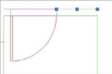
You're ready to extend the wall line. For this operation, you'll use grip editing:
1.
Click the wall line at the top of the plan and to the right of the door to select the line and
expose its grips.
2.
Click the Ortho Mode button in the status bar to turn on Ortho mode. This keeps the wall
line straight as you edit it.
3.
Click the rightmost grip of the line to make it hot.
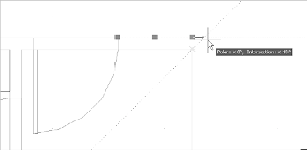
4.
Place the cursor on the upper-right corner of the plan until you see the Endpoint Osnap
marker; then move the cursor away from the corner at a 45° angle. The Osnap Tracking
vector appears at a 45° angle. Notice the small X that appears at the intersection of the
Osnap Tracking vector and the line (see Figure 6.22).
FIGURE 6.22
The Osnap Track-
ing vector
With the Osnap Tracking vector and the line intersecting, click the mouse button. The
line changes to extend exactly 5 units beyond the vertical interior wall of the plan.
5.
Press the Esc key to clear your selection. Then repeat steps 1 through 4 for the horizontal
wall line to the left of the door to extend that line to the left corner (Figure 6.23).