Graphics Programs Reference
In-Depth Information
AutoCAD usually draws a rectangular array from bottom to top and from left to right. You
can reverse the direction of the array by giving negative values for the distance between col-
umns and rows.
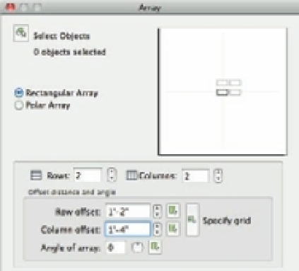
At times, you may want to create a rectangular array at an angle. To accomplish this, enter
the desired angle in the Angle Of Array text box in the Array dialog box. You can also select the
angle graphically by clicking the Pick Angle Of Array button or using the circular slider to the
right of the Angle Of Array text box.
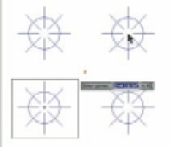
If you need to indicate an array cell graphically, you can do so by using options in the Offset
Distance And Angle group of the Array dialog box (see the bottom image in Figure 6.9). An
array cell
is a rectangle defining the distance between rows and columns (see the top image in
Figure 6.9). You may want to use this option when objects are available to use as references from
which to determine column and row distances. For example, you might draw a crosshatch pat-
tern, as on a calendar, within which you want to array an object. You use the intersections of the
hatch lines as references to define the array cell, which is one square in the hatch pattern.
In the Offset Distance And Angle group, the Pick Both Offsets tool lets you indicate the row
and column distance by placing an array cell graphically in the drawing, as shown in the bot-
tom image in Figure 6.9. You can also indicate a row or column distance graphically by using the
Pick Row Offset button or the Pick Column Offset button to the right of the Pick Both Offsets
button. Clicking the circular slider to the right of the offset text boxes allows you to incremen-
tally change the distance up or down.
FIGURE 6.9
An array cell and
the Array dialog
box tool that let
you graphically
indicate array cells
Click the Pick Both
Offsets tool...
...and then click two points
indicating the array cell.