Graphics Programs Reference
In-Depth Information
In the following exercises, you'll draw a plan view of a bathroom sink as an introduction to
the Osnap Tracking feature. This drawing will be used as a symbol in later chapters.
G
E T T I N G
S
E T
U
P
First, as a review, you'll create a new file. Because this drawing will be used as a symbol for
insertion in other CAD drawings, don't worry about setting it up to conform to a sheet size.
Chances are you won't be printing individual symbols. Here are the steps:
1.
Choose File
New from the menu bar to create a new drawing for your bathroom sink.
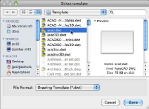
2.
As before, choose acad.dwt from the Select Template dialog box (Figure 3.16) or select
acadiso.dwt if you are using the metric system.
FIGURE 3.16
The Select Tem-
plate dialog box
3.
Click Open to open the new file.
4.
Choose Format
Units from the menu bar.
5.
In the Drawing Units dialog box, choose Architectural from the Type pop-up list and
then click Save. Metric users can use the default Decimal option.
6.
Choose Format
Drawing Limits from the menu bar.
7.
Press ↵ to accept the origin of the drawing as the lower-left corner of the drawing limits.
8.
Enter
48,36
↵ for the upper-right corner. Metric users should enter
122,92
↵.
9.
Type
Z
↵
A
↵ to display the overall area of the drawing set by the limits.
10.
Choose File
Save As from the menu bar to save the file under the name Sink.
If you find that you use the same drawing setup over and over, you can create template files that
are already set up to your own, customized way of working. Templates are discussed in Chapter 6.