Graphics Programs Reference
In-Depth Information
TABLE 3.2:
Scale conversion factors
SCALE FACTOR
FOR ENGINEERING
DRAWING SCALES
DRAWING
SCALE
n
= 1˝
1 0´
2 0´
3 0´
4 0´
5 0´
6 0´
1 0 0´
2 0 0´
Scale factor
120
240
360
480
600
720
1200
2400
SCALE FACTORS FOR
ARCHITECTURAL
DRAWING SCALES
DRAWING
SCALE
n
= 1´- 0˝
1
⁄
16
˝
1
⁄
8
˝
¼˝
½˝
3
⁄
4
˝
1˝
1½ ˝
3˝
Scale factor
192
96
48
24
16
12
8
4
In older drawings, scale factors were used to determine text height and dimension set-
tings. Chances are you will eventually have to work with drawings created by older AutoCAD
releases, so understanding scale factors will pay off later. Printing to a particular scale is also
easier with an understanding of scale factors.
Using Polar Tracking
In this section, you'll draw the first item in the bathroom: the toilet. It's composed of a rectangle
representing the tank and a truncated ellipse representing the seat. To construct the toilet, you'll
use Polar Tracking, which is one of the most versatile drafting tools. Polar Tracking helps you
align your cursor to exact horizontal and vertical angles, much like a T-square and triangle.
In this exercise, you'll use Polar Tracking to draw a rectangular box:
1.
Start a line at the coordinate 5´-7˝,6´-3˝ by entering
L
↵
5´ 7 ˝,6´3 ˝
↵. Metric users should enter
L
↵
171,189
↵ as the starting coordinate. This starting point is somewhat arbitrary, but by
entering a specific starting location, you're coordinated with the figures and instructions
in this topic. You can also use the Line tool in the Tool Sets palette to start the line.
2.
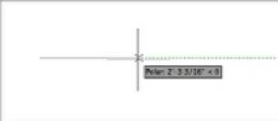
Make sure Polar Tracking is on (the Polar Tracking tool in the status bar should be blue),
and then point the cursor directly to the right of the last point. The Polar Tracking cursor
appears along with the Polar Tracking readout.
3.
With the cursor pointing directly to the right, enter
1´-10 ˝
↵. Metric users should enter
56
↵.
You can use the spacebar in place of the ↵ key when entering distances in this way.