Graphics Programs Reference
In-Depth Information
4.
Click the Precision pop-up list just below the Type pop-up list. Notice the options avail-
able. You can set the smallest unit AutoCAD will display in this drawing. For now, leave
this setting at its default value of 0´-0
1
⁄
16
˝. Metric users will keep the setting at 0.0000.
5.
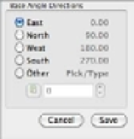
Take a look at the Base Angle Directions group. This group lets you set the direction for the
0° angle. For now, don't change these settings—you'll read more about them in a moment.
6.
Click the pop-up list in the Insertion Scale group. The list shows various units of measure.
7.
Click Inches; if you're a metric user, choose Centimeters. This option lets you control
how AutoCAD translates drawing scales when you import drawings from outside the
current drawing.
8.
Click Save in the Drawing Units dialog box to return to the drawing.
If you use the Imperial system of measurement, you selected Architectural measurement
units for this tutorial, but your work may require a different unit type. You saw the unit types
available in the Drawing Units dialog box. Table 3.1 shows examples of how the distance 15.5 is
entered in each of these styles.
TABLE 3.1:
Measurement systems available in AutoCAD
MEASUREMENT SYSTEM
AUTOCAD'S DISPLAY OF MEASUREMENT
Scientific
1.55E+01 (inches or metric)
Decimal
15.5000 (inches or metric)
Engineering
1´-3.5˝ (input as 1´3.5˝ )
Architectural
1´-3½˝ (input as 1´3-½˝ )
Fractional
15½˝ (input as 15-½˝ )
In the previous exercise, you needed to change only two settings. Let's look at the other
Drawing Units settings in more detail. As you read, you may want to refer to Figure 3.1.