Geology Reference
In-Depth Information
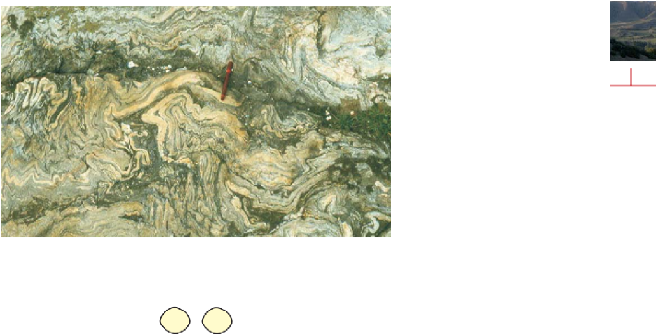
Figure 6.11
Superimposed folding.
A.
Complex
interference structure formed by superimposition
of upright F2 folds on recumbent isoclinal F1 folds
in banded gneiss.
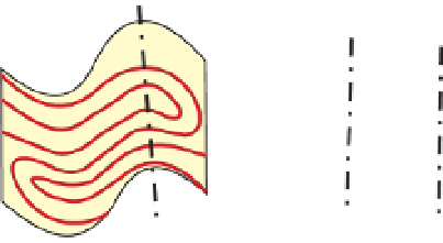
B.
Interference structure formed
by superimposition of F2 flow folds on isoclinal
F1 folds whose axial planes are approximately
perpendicular.
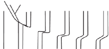
C
,
D
, common patterns found
in superimposed flow folds with perpendicular
axes; in C, both folds are upright; in D, F1 is a
tight overfold (the relationship shown in C gives a
pattern of domes and basins often referred to as
'egg-box' pattern).
6
54
55
F2
F1
F2
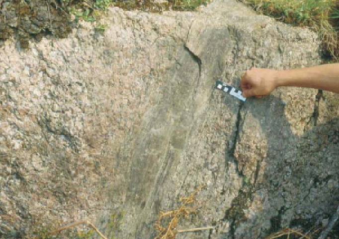
Figure 6.12
Shear zones.
A.
In a simple
shear zone, a zone of ductile strain is
formed between two blocks moving in
opposite directions; the strain increases
towards the centre of the zone.
B.
The
displacement caused by faulting in the
upper brittle layer of the crust may become
transformed into a shear zone in the lower,
more ductile crust. Inspired by a diagram
by J.G. Ramsay (1987).
C.
Shear zone
in previously undeformed granite; a faint
fabric (outlined in white) in the granite to
the left of the shear zone curves gradually
into it; the zone itself is highly strained and
much finer-grained. The left-hand side
of the shear zone has moved upwards in
relation to the right, as in a reverse fault.
F1
A
F2
F2
F2
F2
F1
F1
F1
F1
F1
F1
F2
F2
C
D
B
maximum
strain
zone
displacement
A
normal faults
shear
zone
C
shear zone
B


Search WWH ::

Custom Search