Geology Reference
In-Depth Information
of rotation (i.e. clockwise or anticlock-
wise) in shear zones. In Figure 4.6B,
the fact that the elongated lines are
inclined to the right and the shortened
lines to the left, shows that the block
has undergone
dextral
(right-lateral)
rather than
sinistral
(left-lateral) shear.
At large rotational strains, it is possible
for planes to first contract and later to
extend (as in line 3 in Figure 4.6B), and
this history may be revealed by an ini-
tially folded layer that has subsequently
been pulled apart by later extension.
to make detailed and accurate meas-
urements of strain in one part of a
rock, it will normally be more useful
to take a statistical approach and
obtain a large number of approxi-
mate measurements over a given
area. An important restriction is that
only certain types of rock will contain
objects of known initial shape that can
be used to measure the strain; such
objects are known as
strain markers
.
The best strain markers are initially
spherical and include spherulites
in lavas,
ooliths
in limestones, and
certain reduction spots in slates. The
method is illustrated in Figure 4.7A.
The assumption has to be made that
the strain in the matrix of the rock
corresponds to that in the measured
objects. This only applies if the two
materials have approximately the
same strength. Pebbles in conglomer-
ates are frequently used, but allow-
ance has to be made for their initial
variability. However, if the initial
shape variation is random - that is,
there is no original preferred shape
orientation - the method can give
a reasonable approximation to the
overall strain. The shapes of grain
aggregates and deformed
phenocrysts
in igneous rocks have also been
widely used as strain markers, since
at moderate to large strains these
objects become ellipsoidal. Certain
fossils can also be used, but the geo-
metrical calculations involved can be
quite complex and time-consuming.
Another possibility that avoids the
necessity of measuring the objects
themselves is to measure the spacing
between them. If it can be assumed
that they were originally spaced either
randomly or evenly through the rock
body, the spacing between them gives
a measure of the strain (Figure 4.7B).
The measurement can be simply done
by selecting an XZ plane and counting
the number of intersections along a
traverse in the X direction and compar-
ing it to the number in the Z direction.
A similar exercise in either the XY or YZ
planes will give the strain ratio X:Y:Z.
A third method can be used where
the original unstrained body contains
linear or planar elements (e.g. elongate
crystals in an igneous rock) that had
no initial preferred orientation. This
situation corresponds to that shown
schematically in Figure 4.6. At a strain
of X:Z = 4:1, all but three of the lines
are concentrated within an angle of
35° about the X axis, and at a strain of
X:Z = 16:1, all but one are within an
angle of 22°. Clearly, therefore, at large
4
24
25
The measurement of strain
Because rocks are so variable in
their physical properties, measuring
the strain in any particular part of a
complex rock body will not usually
be applicable to the behaviour of the
whole body. So, rather than attempting
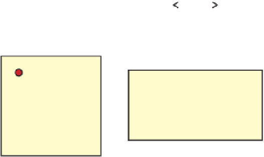
Figure 4.7
Two easy ways to
measure strain.
A.
In a rock
containing evenly spaced
objects (e.g. pebbles or
phenocrysts), measured in the
XZ plane, the mean separation
between the objects in the X
direction compared to the Z
direction gives the X:Z strain
ratio; a similar measurement
in either the XY or YZ planes
gives X:Y:Z.
B.
In a rock
containing objects that can
be assumed to have been
initially spherical, or whose
initial shapes had no preferred
orientation, the mean X:Z ratio
of the strained objects can be
assumed to represent the X:Z
ratio of the rock as a whole,
provided that the strain in the
matrix is equivalent to the
strain in the objects.
A
X=Z
X>Z=2:1
X=Z=1:1
B
X>Z=2:1


Search WWH ::

Custom Search