Environmental Engineering Reference
In-Depth Information
Table 5.9
Values of the
k
Factor for the Calculation of the Rates of
Generator Power
Synchronous generators, inverter
k
= 1
Asynchronous generators, powered up with 95-105% of their
synchronous speed
k
= 2
Asynchronous generators, run up by the mains
k
=
I
l
/
I
r
If
I
l
is unknown
k
= 8
Note: I
l
locked-rotor current,
I
r rated current
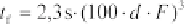
(5.118)
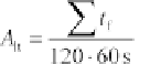
The sum of the flicker after-effect times over an investigation interval of 120
min provides the long-term disturbing flicker factor:
(5.119)
For wind generators, the system flicker coefficient
c
can be estimated from
measurements (VDEW, 1994). This provides the criterion for the permissible
long-term disturbing flicker coefficient:
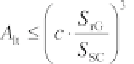
(5.120)
A boundary criterion for the long-term disturbing flicker factor
A
lt
of a single
wind generator is:
(5.121)
The higher the number of rotor blades the lower is the system flicker coefficient
c
. If the generator is connected via an inverter to the mains, the flicker
coefficient is usually smaller than that of systems connected directly to the
mains. If multiple wind generators of a wind park are connected to the same
knot of the medium- or high-voltage system, the resulting system flicker
coefficient
c
res
of
n
similar generators becomes:
(5.122)
The problem of harmonics have already been discussed in detail in the chapter
on photovoltaics (Chapter 4). Since the current of wind generators is usually
fed into medium- or high-voltage systems, the limiting values are different from
those of the low-voltage systems to which photovoltaic systems are usually
connected.
If one of the guide values is exceeded, technical measures must be put in
place to mitigate them. If the short-circuit power of the mains is too low,