Environmental Engineering Reference
In-Depth Information
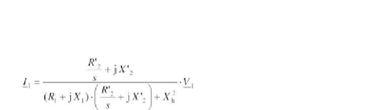
Substituting the current and
X
1
=
X
1σ
+
X
h
into the voltage equation of the
stator and solving for
I
1
provides:
(5.99)
This equation describes the
circle diagram
of the stator current. If the stator
voltage
V
1
and the mains frequency
f
1
as well as the resistances and reactances
remain constant, the stator current depends only on the slip
s
.
Figure 5.29 shows the curve of the stator current
I
1
as a function of the
slip. The stator voltage
V
1
is the reference value on the real axis. The current
moves on a circle depending on the operating conditions of the machine. This
circle is named after
Heyland and Ossanna
. The stator resistance
R
1
is
neglected for the Heyland circle. This circle clearly shows that the current at
the stationary condition is much higher than that near zero-load operation.
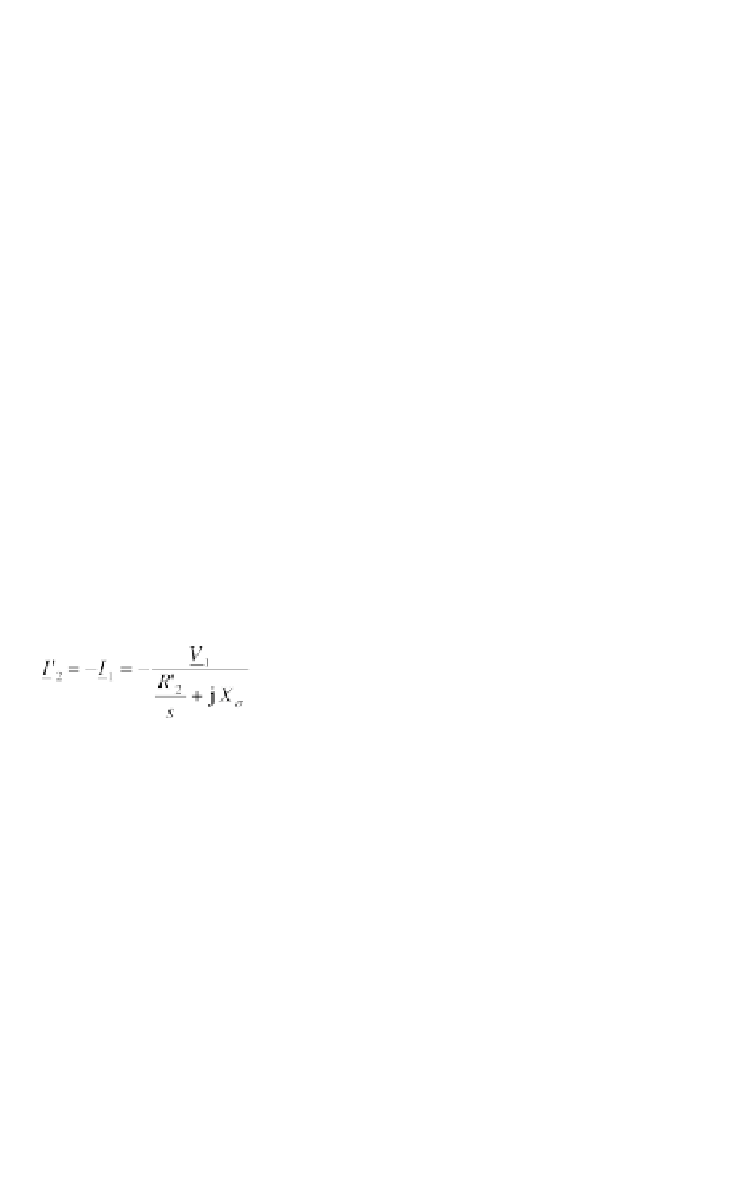
With the major simplification
X
h
, the current through
X
h
becomes
zero. Figure 5.30 shows the simplified equivalent circuit with
R
1
~
0 and
X
σ
=
X
1σ
. This equivalent circuit is used for the derivation of the equation
of Kloss in the section headed 'Speed-torque characteristics and typical
generator data' on p223.
The simplified equivalent circuit provides a simplified equation of the
current:
+
X
'
2σ
(5.100)
Figure 5.29
Circle Diagram for the Estimation of the Stator Current
According to Heyland and Ossanna