Environmental Engineering Reference
In-Depth Information
Table 5.7
Speed and Slip at Different Operating Conditions for an
Asynchronous Machine
Operating condition
Speed
Slip
Standstill (short circuit)
n
= 0,
n
S
> 0
s
= 1
Motor mode
0 <
n
<
n
S
0 <
s
< 1
Synchronous speed (no load)
n
=
n
S
s
= 0
Generator mode
n
>
n
S
s
< 0
Brake mode
n
< 0,
n
S
> 0
1 <
s
<
currents. If the asynchronous generator works in an island grid, a capacitor
bank can generate reactive currents and provide the required
reactive power
.
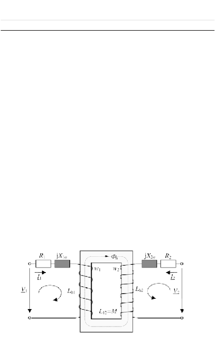
Equivalent circuits and circle diagrams for the stator current
The electrical structure of an asynchronous machine is similar to a transformer
that consists of two coupled windings. The windings of an ideal transformer
are coupled free of leakages. A real transformer has leakage fields and ohmic
losses that can be considered by additional resistances and reactances in the
equivalent circuit (see Figure 5.27).
Hence, the equations for the voltages of the transformer become:
(5.90)
(5.91)
With the number of turns per phase
w
1
and
w
2
and
I
2
=
w
1
•
I
'
2
=
tr
•
I
'
2
;
V
2
=
w
2
V
'
2
tr
-1
;
R
2
=
R
'
2
•
tr
-2
,
X
2σ
=
X
'
2σ
•
tr
-2
,
X
h2
=
X
h
•
tr
-2
,
X
12
=
X
h
•
tr
-1
,
X
h1
=
X
h
as well as
X
h1
=
X
h
, the voltage equations related to the primary side
become:
(5.92)
Figure 5.27
Ideal Transformer with Resistances and Reactances