Environmental Engineering Reference
In-Depth Information
Drag forces
, which have been described in the section about drag devices
(see p191), also have effects on lift devices:
(5.34)
However, the buoyancy force on a drag device is much higher than the drag
force. The ratio of both forces is called the
lift-drag ratio
ε
:
(5.35)
Some references also use the inverse ratio. Good rotor profiles can reach lift-
drag ratios of up to 400.
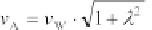
The
apparent wind speed
:
(5.36)
used in the equations above is calculated from the real wind speed
v
W
and the
circumferential speed
u
(see Figure 5.7). With the tip speed ratio
λ
=
u
/
v
w
, the
apparent wind speed becomes:
(5.37)
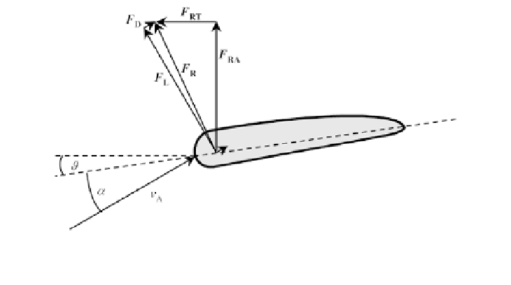
Figure 5.8 shows the ratio of the drag force
F
D
to the buoyancy force
F
L
.
Vector addition of both forces provides the resultant force:
F
R
=
F
D
+
F
L
(5.38)
The resultant force can be subdivided into an axial component
F
RA
and a
tangential component
F
RT
. The tangential component
F
RT
of the resultant force
causes the rotor to turn.
Underpressure
Chord
Rotor plane
Overpressure
Figure 5.8
Ratio of the Forces for a Lift Device