Environmental Engineering Reference
In-Depth Information
commutation. If the circuit can provide this energy itself, it is called self-
commutation; however, such a circuit needs energy storage. An externally
commutated inverter is not suitable for stand-alone operation. The grid defines
the switching points of externally commutated inverters, whereas a self-
commutated inverter must determine them itself. The voltage of grid-connected
inverters must be synchronized with the grid voltage.
Besides the type of commutation, inverter technologies can be classified as:
•
square-wave or trapezium inverters
•
stair-step inverters
•
pulse-width modulated or resonance inverters.
Other inverter differences depend on the operating mode. Grid-connected
inverters have to fulfil stringent criteria to maintain high power quality.
Therefore, amplitude, frequency and current shape must follow the rules of
the grid operators. For grid-protection, the inverter must switch off
immediately if the grid fails. However, island inverters do not have to meet
these strict criteria.
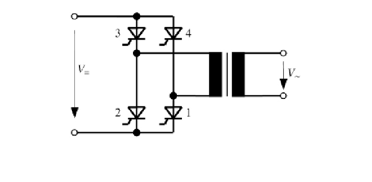
Square-wave inverter
A very simple inverter circuit is the
two-pulse bridge connection (B2
connection)
shown in Figure 4.53. It consists of four thyristors. A transformer
connects the circuit to the grid.
Thyristors 1 and 3 work together, as do thyristors 2 and 4. If these two
groups switch periodically, they generate a square-wave alternating current at
the transformer. Thyristors 1 and 2 can be replaced by non-controllable diodes
for simplification; in this case, only half of the bridge must be controlled. This
connection is then called a half-controlled bridge connection. The switching of
the thyristors is delayed by the control angle
compared to the voltage zero
crossing. Figure 4.54 shows the current of a B2 connection.
This shape differs significantly from that of a sinusoidal wave. To assess
the current quality, Fourier analysis or
harmonic analysis
is used.
α
Figure 4.53
Two-pulse Bridge Connection (B2)