Environmental Engineering Reference
In-Depth Information
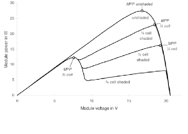
Figure 4.28
P-V Characteristic of a Module with 36 Cells and Two Bypass
Diodes. A Single Cell is Shaded to Different Degrees; All Other Cells Are
Fully Irradiated (
E
= 574 W/m
2
,
T
= 300 K)
Figure 4.26 illustrates bypass diode integration across cells and strings of
cells. The bypass diode switches as soon as a small negative voltage of about
-0.7 V is applied, depending on the type of diode. This negative voltage occurs
if the voltage of the shaded cell is equal to the sum of the voltages of the
irradiated cells plus that of the bypass diode.
Figure 4.27 shows the shape of I-V characteristics with bypass diodes
across a varying number of cells. In this example, one cell is 75 per cent
shaded. It is obvious, that the significant drop in the I-V characteristics moves
towards higher voltages with decreasing number of cells per bypass diode. This
occurs because the bypass diode switches earlier. It also reduces the power loss
and the strain on singles cells.
Figure 4.28 shows the power-voltage characteristics of a module with two
bypass diodes across 18 cells for different shading situations. Depending on
the degree of shading, the MPP shifts and high losses occur although bypass
diodes are integrated.
Parallel connection of solar cells
A parallel connection of solar cells is also possible. Parallel connections are
less often used than series connections because the associated current increase
results in higher transmission losses. Therefore, this section gives only a rough
overview on parallel connection.
Parallel-connected solar cells as shown in Figure 4.29 all have the same
voltage
V
. The cell currents
I
i
are added to obtain the overall current
I
: