Environmental Engineering Reference
In-Depth Information
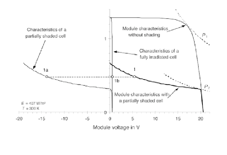
Figure 4.25
Construction of Module Characteristics with a 75 per cent
Shaded Cell
ranges of this characteristic only occur if the current in the partially shaded
cell is higher than the cell short circuit current. This is only possible in the
negative voltage range of the shaded cell, and this cell then operates as a load
that can be described by the equivalent circuit shown in Figure 4.19.
Figure 4.25 shows the determination of one point of the module
characteristic (1). The module voltage for a given current is the sum of the
voltage of the partially shaded cell (1a) and 35 times the voltage of the
irradiated cells (1b). The total module characteristic of the shaded case is
calculated this way point by point for different currents.
It is obvious that
cell shading
reduces the module performance drastically.
The maximum module power decreases from
P
1
= 20.3 W to
P
2
= 6.3 W,
i.e. by about 70 per cent, although only 2 per cent of the module surface is
shaded. The partially shaded solar cell operates as a load in this example. The
dissipated power of the shaded cell is 12.7 W and is obtained when the module
is short circuited.
Other shading situations at higher irradiances can increase the power
dissipated in the shaded cell up to 30 W. This will heat the cell significantly
and may even destroy it. So-called
hot spots
, i.e. hot areas about a millimetre
in size, can occur where the cell material melts or the cell encapsulation is
damaged.
To protect single cells from hot spot related thermal damage, so-called
bypass diodes
are integrated into the solar modules in parallel to the solar cells.
These diodes are not active during regular operation, but when shading occurs,
a current flows through the diodes. Hence, the integration of bypass diodes
eliminates the possibility of high negative voltages, and in the process
eliminates the increase in cell temperature of shaded solar cells.