Environmental Engineering Reference
In-Depth Information
Figure 4.19
Two-diode Equivalent Circuit with Second Current Source to
Describe the Solar Cell Breakdown at Negative Voltages
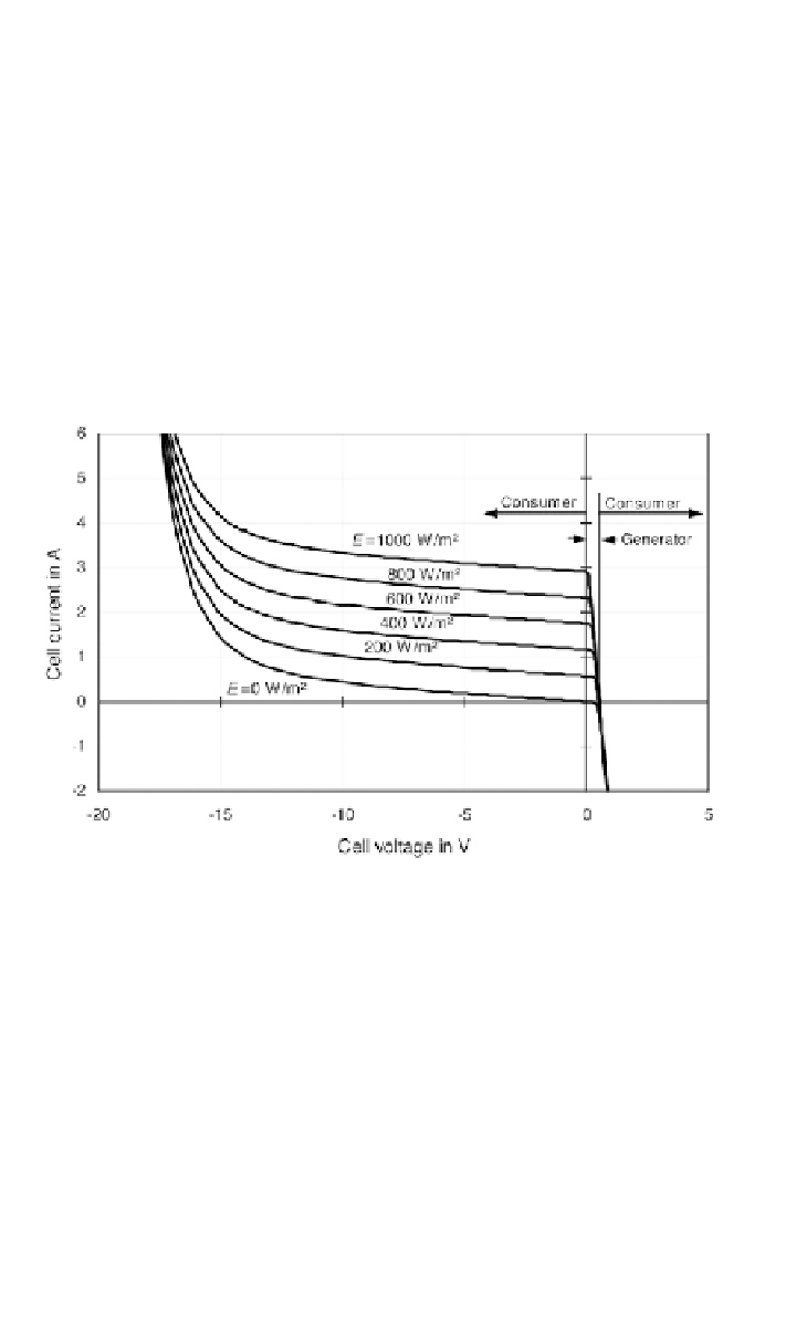
Figure 4.20
I-V Characteristics of a Polycrystalline Solar Cell over the
Full Voltage Range
Figure 4.20 shows the I-V characteristics of a polycrystalline solar cell over the
full voltage range obtained with the parameters
I
S1
=
3
•
10
-10
A,
m
1
= 1,
I
S2
=6
•
10
-6
,
V
Br
= -18 V,
b
= 2.33 mS
and
n
= 1.9. In this instance, the series resistance is relatively high due to the
inclusion of the connections. In the given figure, cell voltage and current are
positive in the quadrant where the solar cell is generating power. If the cell
voltage or current becomes negative, the solar cell is operated as load.
Therefore, an external voltage source or other solar cells must generate the
electrical power required.
A,
m
2
= 2,
R
S
= 0.13
Ω
,
R
P
=30
Ω
Further electrical solar cell parameters
Besides the described correlations of solar cell current and voltage, further