Environmental Engineering Reference
In-Depth Information
Using the above equation for the collector power output, the collector flow
rate becomes:
(3.20)
and the collector flow rate with respect to the collector or absorber surface is:
(3.21)
For instance, if a flat-plate collector with
η
0
= 0.8 and
a
= 4 W/(m
2
K)
heats up a heat transfer medium with heat capacity
c
= 0.96 Wh/(kg K) from
ϑ
Cin
∆ϑ
HTF
= 10 K), the required collector
flow rate for an ambient temperature of
= 35°C to
ϑ
Cout
= 45°C (i.e. by
ϑ
A
= 20°C and an average
= 40°C at an irradiance of
E
= 800 W/m
2
is
m
•
' =
collector temperature
ϑ
C
58.3 kg/(m
2
h).
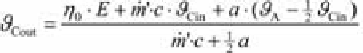
Replacing
(3.22)
and
(3.23)
in the equation for collector flow rate
m
•
' provides the
collector outlet
temperature
ϑ
Cout
for a given collector inlet temperature
ϑ
Cin
:
(3.24)
If the collector flow rate is reduced to 18 kg/(m
2
h) and the collector inlet
temperature
ϑ
Cin
is kept constant in the example above, the collector outlet
temperature
ϑ
C
increases to 50°C. As a result, the collector efficiency decreases from 70 to 65
per cent. These or even smaller flow rates are used in thermosyphon and so-
called low-flow systems.
The collector flow rate may also be given in litre/h or litre/(m
2
ϑ
Cout
increases to 65°C and the average collector temperature
h). This
volume flow V
•
depends on the
mass flow m
•
and the density
ρ
:
(3.25)
For water with a density slightly lower than 1 kg/litre (or a density of about
1.06 kg/litre with added antifreeze agents), the numerical value of the
volumetric flow is nearly equal to that of the mass flow.
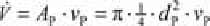
The cross-sectional area
A
P
of the pipes in the collector cycle and the flow
velocity
v
P
of the heat transfer medium defines the necessary
pipe diameter d
P
using
as: