Graphics Programs Reference
In-Depth Information
7.
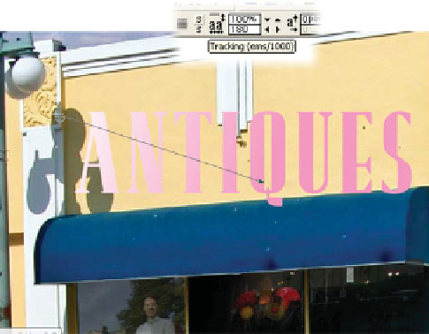
With the Fill Tool, drag from
just outside the left of the
text to a point around the
Q
.
You do this for a lighting
effect; the sun is casting from
about 10 o'clock and actual
extruded text on the face of
the building would have a
little more illumination at its
left than its right.
Choose the Extrude Tool, and
8.
then click the Apply Extrusion
button on the Infobar (the
same icon design as the “3D”
Extrude Tool icon) to set an
initial extrusion.
Showtime: Although you can drag on the face of an
9.
extruded shape to change its angle of rotation, precision
is required here to match the perspective of the building
front. For that, you'll use the angle settings on the
Infobar instead of manual adjustment. First, choose
Angle 1 from the Extrusion Parameter drop-down list
to the right of the 3D button on the Infobar. Angle
1 (unless a 2D shape has been rotated) controls the
top-to-bottom rotation, called Y axis rotation in most
3D modeling programs. Set this to
20
—type in the
value and then press
ENTER
or drag on the slider until
your view shows just a little of the bottom facets of the
lettering.
Choose None as the Bevel Type from the drop-down list.
10.
The fancier the text looks, the more illustrative and less
photorealistic it will appear in the composition. Less is
more in the art of misdirection in magic.
Choose Angle 2 from the drop-down list; this controls
11.
the left-to-right rotation, called X axis rotation in
modeling programs. Set the Angle 2 value to about
20 so the text is facing left a little. Angle values are
interdependent, and adjusting one value occasionally
requires that you go back and re-tune another value.
Place your cursor over the side, not the face of the 3D
12.
text. When your cursor changes to a two-headed arrow
(not the four-headed one that controls object rotation),
you can drag to increase the depth of the extruded text.