Biomedical Engineering Reference
In-Depth Information
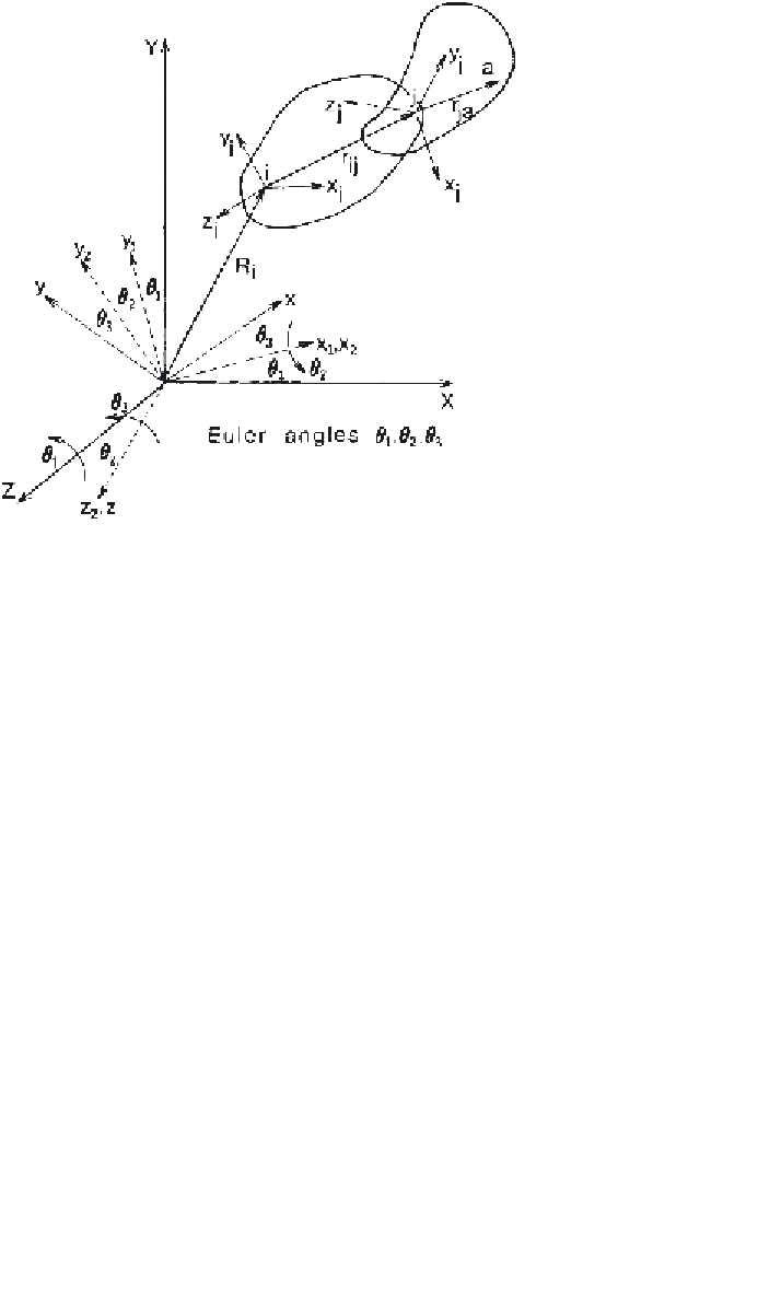
Figure 8.4
Three-dimensional link-segment system showing the three Euler angles
θ
1
,
θ
2
,and
θ
3
andthetwoLRSforthe
i
th and
j
th segments.
R
j
=
R
i
+
[
φ
]
r
ij
=
V
i
+
[
φ
]
v
ij
+
[
φ
]
ω
r
ij
V
j
where [
φ
]isa3
×
3 transformation matrix known as the direction cosines
matrix (DCM) and
˜
ω
is a 3
3 angular velocity matrix. The elements of
both matrices are greatly dependent on the angular system used. Among the
common parameters used to describe the angular orientation of a segment in
space are Euler angles. For Euler angles that follow the order of rotation
zxz
,
the angular orientation of an LRS (reference
xyz
in Figure 8.4) is represented
as the result of a sequence of three rotations. The first rotation
θ
1
is carried out
about the Z axis. It results in the auxiliary reference
(x
1
,
y
1
,
z
1
)
. The second
rotation through the angle
θ
2
about the
x
1
axis produces a second reference
(x
2
,
y
2
,
z
2
)
. The third rotation through the angle
θ
3
about the
z
2
axis gives the
final orientation. Let
c
1
and
s
1
be cos
(θ
1
)
and sin
(θ
1
)
, respectively. It can be
seen that the transformation matrices associated with these rotations are:
×
⎡
⎤
⎡
⎤
⎡
⎤
c
1
s
1
0
100
0
c
3
s
3
0
⎣
⎦
,
⎣
⎦
,
⎣
⎦
[
φ
1
]
=
−
s
1
c
1
0
001
[
φ
2
]
=
c
2
s
2
[
φ
3
]
=
−
s
3
c
3
0
001
0
−
s
2
c
2


Search WWH ::

Custom Search