Geology Reference
In-Depth Information
detect speci
c parts of the EM spectrum. The energy
detected depends on the interaction of the energy with
the surface being analyzed, generating spectra that are
distinctive for various properties of the surface. For exam-
ple, sunlight shining on a planetary surface can be
re
ected, absorbed, and/or transmitted, depending on the
EM wavelength, the temperature, and characteristics of
the surface materials, such as composition and grain size.
Remote sensing systems are classi
ed as either passive
or active. Passive system use natural radiation, such as
sunlight, whereas active systems illuminate the surface
with an arti
cial energy source. For example, radar imag-
ing systems beam energy toward a surface, some of which
is re
ected and then recorded by a radar sensor. Active
systems also include non-imaging systems, such as laser
and radar altimeters, which measure the distance from the
instrument to the surface.
2.5.1 Visible imaging data
Nearly every spacecraft sent in the exploration of the Solar
System has carried a camera or imaging system as part of
its scientific payload. Currently, most imaging systems
use charge-coupled devices (CCDs) as the detector,
rather than
film. However, in planetary geomorphology,
images from previous missions are still useful, and it is
important to be familiar with the imaging systems used in
these missions, as described in
Appendix 2.1
.
CCDs were invented in 1969 by Bell Laboratories and
are used in a variety of solid-state imaging devices. Today,
modern digital cameras all use CCD technology, including
simple cell-phone cameras and sophisticated video systems.
A CCD
consists of a layer of metallic electrodes and
a layer of silicon crystals, separated by an insulating layer of
silicon dioxide. When used as an imaging system, the CCD
chip is structured as an array of picture elements, or pixels.
Light focused onto the chip by a lens causes a pattern of
electrical charges to be created. The charge on each pixel is
proportional to the amount of light received and provides an
accurate representation of the scene. Each charge can be
transmitted separately and then reconstructed using conven-
tional image-processing techniques.
CCD imaging systems can be either line arrays or two-
dimensional arrays. In line arrays, a single line of CCDs
sweeps across the scene as the spacecraft (or aircraft)
moves over the terrain, building up the image. Two-
dimensional arrays consist of a chip with CCDs on an
X
“
chip
”
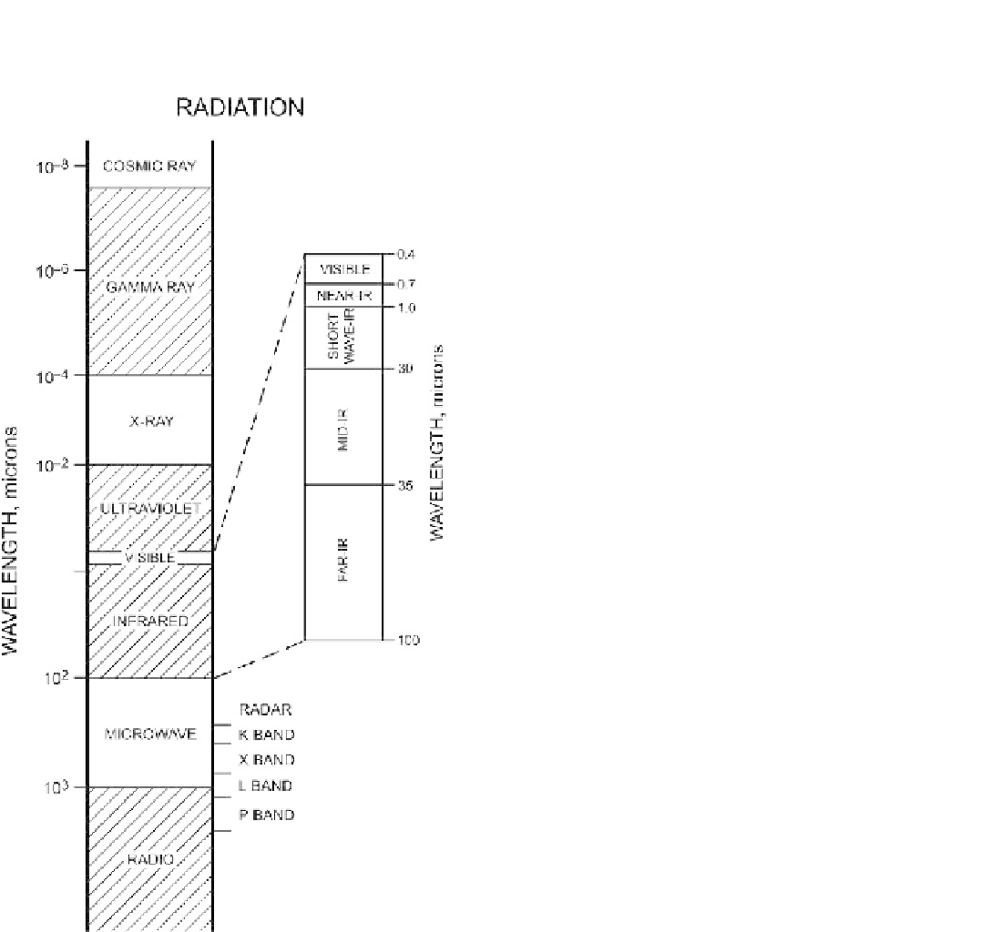
Figure 2.14. The electromagnetic (EM) spectrum, showing
important wavelengths used in remote sensing. Radar systems are
subdivided and given letter designations that were arbitrarily
assigned (see
Table 2.1
).
in Solar System exploration, with most information com-
ing from spacecraft located well above the surface.
Remote sensing instruments make use of electromag-
netic (EM) radiation (
Fig. 2.14
), which is generated
whenever there is a change in the size or direction of an
electrical or magnetic
field. For example, electrons shift-
ing from one orbit to another orbit around an atomic
nucleus results in X-rays and visible (light) radiation,
while
fluctuations in the electrical/magnetic
field generate
microwaves and radio waves of the sort used in radar
systems. Remote sensing instruments are designed to
Y coordinate system and are used as framing cameras in
which the CCDs record the scene as a
“
snapshot.
”
-