Graphics Programs Reference
In-Depth Information
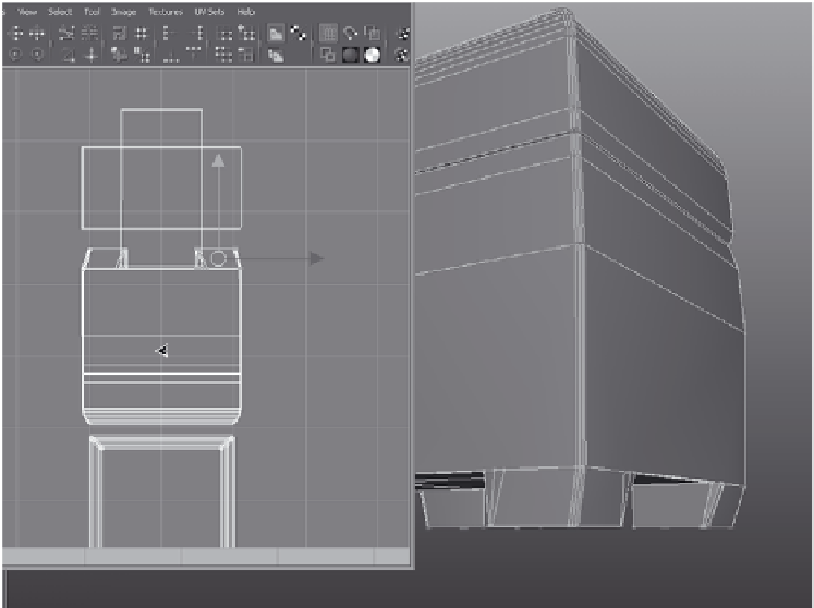
Figure 7.122
Place the front of
the back foot's UVs.
9. The back foot's UVs lie directly behind the front
foot's UVs, which you laid out in step 7. Rotate
the UVs (90 degrees again) with the Polygons
➔
Rotate command, as you did before, and then
position and scale the UVs as shown in Fig-
ure 7.122. They fit exactly behind the front foot.
10. Repeat steps 5 through 9 for the front and back
feet on the front right side of the box.
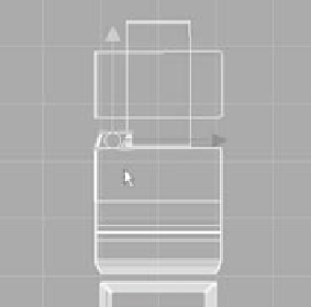
Figure 7.123
Place the UVs for
the fronts of the
two feet on the
right side of the
box's front.
F
ront UV layout
(upside down)
Front of box
Right side
Front and back feet UV shells
11. Let's move to the right side of the box. Select a front face for the foot on the left on
the right side of the box. Again, it sounds confusing, but reference Figure 7.124 for
clarification. You should be getting the hang of what you're doing. Save your work.
12. In the UV Texture Editor, select one UV from the selected face, and then choose
Select
➔
Select Shell. (See Figure 7.125.)
13. Check to see where the UVs for the right side of the box are laid out in the UV Tex-
ture Editor in the earlier Figure 7.111. Rotate, scale, and place these foot UVs as
shown in Figure 7.126.