Graphics Programs Reference
In-Depth Information
5. With those edge loops selected, choose Edit Mesh
➔
Bevel
r
to open the Options box
for the Bevel command. Set Width to 1.0 and Segments to 2, as shown in Figure 6.36.
Click Bevel to create the beveled edge shown in Figure 6.37. It's not quite as round as
it should be, but you'll tackle that with a Smooth operation in the following steps.
Figure 6.36
Settings for the
Bevel operation
Smoothing the Panel
Next, you'll smooth the panel for a better fit to
the real panel and a nicer look overall. Because the
panel isn't as rounded as you'd like, you'll want to
add a Smooth to the mesh, as you did in Chapter 4,
“Beginning Polygonal Modeling” with the hand
model. With the panel mesh selected, press 3 to
display the panel as it will look after it's smoothed.
Notice that the panel looks subtly but appreciably
better with the Smooth preview. However, the bot-
tom of the panel becomes too smooth, as you can
see in Figure 6.38. To fix this, you'll add divisions
to the bottom in the next step:
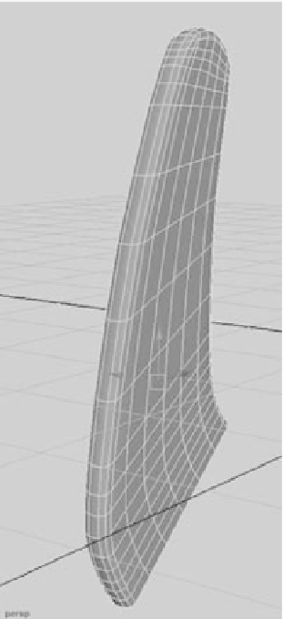
1. Press 1 to return to the normal view of the mesh.
2. Use the Insert Edge Loop tool to insert three new edge loops at the bottom of the
panel, as shown in Figure 6.39. Toggle between previews 1 and 3 to see how much
better the smoothing will look at the bottom.
3. Now for the Smooth operation. Select the panel, and make sure you're back in nor-
mal mesh view by pressing 1. Choose Mesh
➔
Smooth
r
. In the Options box, make
sure Exponentially is selected and Division Levels is set to 1 (the default settings), as
shown in Figure 6.40. Click Smooth. The A panel should look much nicer. Check it
against the reference planes, and it should fit better.
Figure 6.37
The rounded edges after the Bevel