Graphics Programs Reference
In-Depth Information
Keep in mind that when you take a photo, in most cases, there will be
perspective shift
or parallax in the image. Because of that shift, the different views of the same object will
never exactly line up. As you can see in Figure 6.5, the height of the wagon doesn't line
up between the front view and the back view, even though all the other major elements
of the wagon are in alignment. This is due to perspective shift. Because the handle of the
wagon is farther back from the lens of the camera in the front view, it appears lower in
the frame than the handle in the back view.
Complete accuracy isn't what you're after in this situation. You just want to have a
reasonable reference, and this will be more than adequate. Now, you'll import the images
and create the model reference planes on which to work.
Creating Reference Planes for the Images
The reference views of the wagon have already been created for you. You can find them in
the
Sourceimages
folder of the RedWagon project. They're shown in Table 6.1. Hoorah!
Table 6.1
Reference Views
and Sizes
Filename
View
image Size
aSpect Ratio
714
×
783
RedWagonFront.jpg
Front
0.912:1
1024
×
829
RedWagonSide.jpg
Side
1.235:1
1024
×
687
RedWagonTop.jpg
Top
1.490:1
Why is the image resolution important? Well, it's not so much the resolution of the
photos, but rather the aspect ratio of each image. To properly map these images onto the
planes you'll use in Maya, each plane has to be the same ratio in scale as its image. For
example, an image that is 100
×
50 pixels has an aspect ratio of 2:1 and is, therefore, a
wide horizontal rectangle. For it to map properly, the plane on which it's mapped in Maya
must also have a scale ratio of 2:1, so that it's also a wide horizontal rectangle. Otherwise,
the image may distort. The more accurate your model needs to be, the more accurate
your photos and their planes need to be.
You'll need to create three planes for each of the three views. First, make sure Inter-
active Creation is turned off, and then follow these steps:
1. In the Front view panel, create a polygonal plane by choosing Create
➔
Polygon Primi-
tives
➔
Plane
r
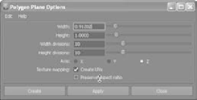
. This plane is for the front image, so in the Options box set Axis to
Z, Width to 0.912, and Height to 1.0. Make sure the check box for Preserve Aspect
Ratio is deselected, as shown in
Figure 6.6. Setting Axis to Z will
place the plane properly in the
front view.
Figure 6.6
Creating a plane for
the top view