Graphics Programs Reference
In-Depth Information
the deformer's options as needed. Click bend1 in the Channel Box to expand the
deformer's attributes shown in the figure.
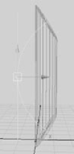
3. Click Curvature, and enter a value of
1
. Notice that the cylinder takes on an odd
shape, as shown in Figure 5.52. The Bend deformer itself is bending nicely, but the
geometry isn't. As a matter of fact, the geometry is now offset from its original loca-
tion. It's offset because there aren't enough divisions in the geometry to allow for a
smooth bend.
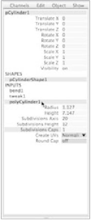
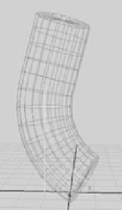
4. Select the cylinder, and click polyCylinder1 in the Channel Box to expand the shape
node's attributes. Enter a value of
12
for the Subdivisions Height attribute (see Fig-
ure 5.53), and your cylinder will bend with the deformer properly, as shown in
Figure 5.54.
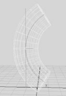
5. Try adjusting the Bend deformer's Low and High Bound attributes. This allows you
to bend one part of the cylinder without affecting the other. Figure 5.55 shows the
cylinder with the Bend deformer's High Bound set to 0.25 instead of 1. This causes
the top half of the cylinder to bend only one quarter of the way up and continue
straight from there.
Experiment with moving the Bend deformer, and see how doing so affects the geom-
etry of the cylinder. The deformer's position plays an important role in how it shapes an
object's geometry.
Figure 5.52
Notice the problem
with this cylinder?
Figure 5.55
Using the High Bound
to change the effect of
the Bend deformer
Figure 5.54
The cylinder bends prop-
erly now that it has the
right number of divisions.
Figure 5.53
Increase Subdivisions
Height to 12.