Graphics Programs Reference
In-Depth Information
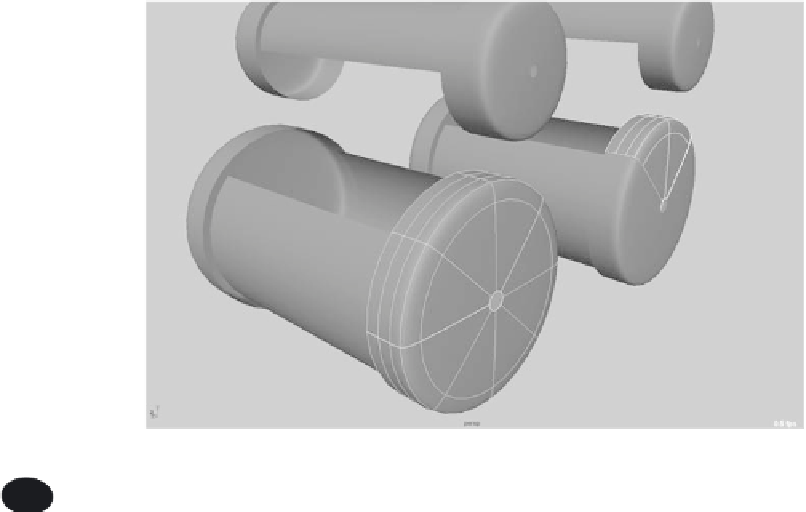
5. You need to prep the end cap to connect to the cylinder, by cutting a pie piece out
of the cap, to line it up with the cut cylinder. On the end cap, select two isoparms
to form a V that lines up with the cut edges of the main cylinder, as shown in Fig-
ure 5.33. Then, choose Edit NURBS
➔
Detach Surfaces. Doing so cuts the V section
out of the end cap. This aligns the end cap and the cylinder geometry at the edges so
you can create a smooth connection between them in the next few steps.
Figure 5.33
Select two isoparms
and detach the
surfaces.
You can load the file
NURBS_pump_v02.mb
from the Locomotive project to compare your
work with it; or, if you skipped the previous steps, you can proceed from here to
attach the end cap.
6. You need to pull the end of the cylinder to line it up with the edge of the end cap.
Select the end four vertical hulls, as shown in Figure 5.34, and move them so that the
edges of the cylinder and end cap align. Repeat this to line up the other end of the
cylinder with the other cap.
7. Create the pieces to connect the caps to the cylinder using lofts. Right-click the
cylinder, and choose Isoparm from the marking menu. Select the edge isoparm on
the cylinder. Right-click the end cap, and choose Isoparm from the marking menu.
Shift+click the edge isoparm of the end cap, as shown in Figure 5.35. Choose Sur-
faces
➔
Loft
r
. Make sure you're using the default settings for the loft: in the Options
box, choose Edit
➔
Reset Settings.
8. The previous step creates a surface to bridge the cylinder and the end cap. You'll
notice that it's rather jagged—almost a diamond shape as opposed to a smooth ring.
With the loft selected, press 3 on the keyboard to see it with a smooth display in the
panel. Figure 5.36 shows the loft.