Graphics Programs Reference
In-Depth Information
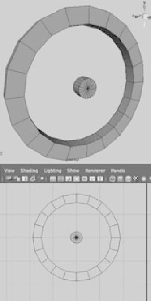
4. The wheel spokes are next. You'll create the
hub of the spokes with a poly cylinder scaled
to
X
and
Z
= 0.25 and
Y
= 0.12, so it's slightly
thinner than the rim. Rotate the hub 90 degrees
in
Z,
and place it in the middle of the rim. It
helps to snap both the hub and the rim to the
same grid point to make sure they're centered
and aligned (see Figure 4.85).
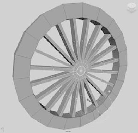
5. Choose the Edit Mesh menu, and make sure
the Keep Faces Together option at the top of
the menu is unchecked. Select the outer ring
of faces on the hub, and extrude them out to
meet the rim, as shown in Figure 4.86.
6. Create a poly cube, and shape it as shown in
Figure 4.87 to place it against the rim of the
wheel on one side. This is where the steam
drive's arm will connect to the wheel.
7. Group the pieces together, and name the
node
large_wheel
. Center the pivot on the
hub by choosing Modify
➔
Center Pivot. If
your geometry isn't perfectly symmetrical,
the pivot may not center properly; you'll have
Figure 4.85
Create the hub for the wheel's spokes.
Figure 4.86
Extrude the outer faces of the hub to create the spokes.
Figure 4.87
Create a plate to which the steam drive's arm will connect.