Information Technology Reference
In-Depth Information
The user consults with the KBES for determination of appropriate machining units and then
s/he uses the CAD system for designing the required SPM. The CAD system used in this
work is SolidWorks which provides user with a 3D modelling environment. It is customized
for SPM design by developing a feature library containing 3D models of standardized SPM
components. As shown in Figure 12 the feature library contains a number of folders, each
containing a group of SPM components. When the user wishes to insert a component, s/he
simply opens the corresponding folder and double clicks on the desired component.
Component's model is extracted from the library and can be easily placed in the desired
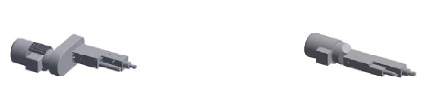
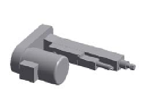
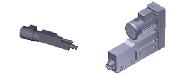
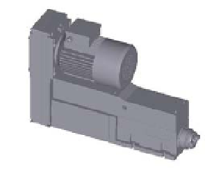
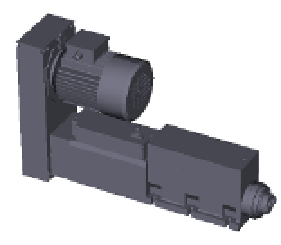
position and orientation within modelling environment. Figure 13 shows different 3D solid
models of quill units (MONOmasters) restored in the feature library, and Figure 14
represents the major steps of processing a typical drilling operation and the way that
various components of the system are used in different activities.
BEM06
BEM03
BEM06D
BEM12
BEM012D
BEM20
BEM25H
BEM28
Fig. 13. 3D solid models of eight quill units (MONOmasters) restored in the feature library