Information Technology Reference
In-Depth Information
3.6 SPM layout
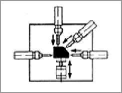
Generally there are two layouts for SPMs; single-station and multi-station. In the former
method the workpiece is held in a fixed position where machining and sliding units are
positioned around it such that they can process the part from different directions. The part is
machined by a single machining unit or by multiple machining units. In the case of multiple
machining units they may process the part simultaneously or in sequence depending on the
geometry of the workpiece and machining features. This layout is shown in Figure 10(a). In
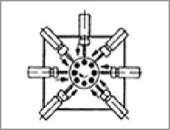
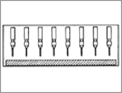
latter method the workpiece is transferred from one station to another until it is processed in
all stations. The number of machining stations varies from two to twelve. Transferring
workpiece between stations is performed by rotational or linear motions. The rotational
motion is provided by indexing tables and the linear motion can be performed by use of
sliding units or other methods. Figures 10 (b) to 10(e) illustrate different multi-station
layouts. The layout of the machine and positioning all the machining and sliding units, the
number of stations in case of multi-station processing, and workpiece transferring method
between stations are decided by machine designers considering technical and productive
measures. In general a higher production rate is achieved in the multi-station method
because of simultaneous machining of several workpieces in multiple machining stations.
(a)
(b)
(c)
(d)
(e)
Fig. 10. Different layouts for SPMs; (a) single-station, (b) special application, (c) transfer
machine, (d) rotary machine, and (e) in-line drilling machine (Photos: Suhner)
3.7 Control system
Before designing the control system, the unit motion diagrams representing reciprocating
motions of all units should be prepared. These diagrams explicitly represent speed and
magnitude of motion of each unit, exact start/stop times, and its position at any time. As
described earlier, the motion of units is often provided by hydraulic and pneumatic
cylinders, or servo-motors. Start and stop signals of motion are usually issued by a
programmable logic controller (PLC) that is programmed based on the unit motion
diagrams.