Environmental Engineering Reference
In-Depth Information
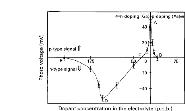
Figure 3.5
PECresultstoshowthatZnSecanbedopedtoproducebothn-
andp-typematerialsbyaddingrelevantimpuritiesintotheelectrolyticbath
[15].
the magnitude indicates the quality of the depletion layer formed at
theinterface.BothmetalsandinsulatorsshowazeroPECsignaldue
tonon-formationofausefuldepletionregion.Metalsformextremely
thin depletion layers, and insulators form extremely thick depletion
layers, producing a zero PEC signal inboth cases.
Figure 3.5 shows the ability of extrinsic doping of electrode-
posited ZnSe layers [15]. An aqueous electrolyte containing 0.1M
ZnSO
4
and 10
−
5
MSeO
2
forms p-ZnSe when grown at
∼
65
◦
C with
pH
=
2.00
∼
2.50. The figure shows the variation of a PEC signal
as a function of external doping of the material. Undoped material
indicates p-type conductivity, showing
∼
50 mV, as shown by the
vertical axis of Fig. 3.5 (point A). The horizontal axis shows the
amount of dopant added to the bath in parts per billion (ppb)
level. However, it should be noted that the amount of dopant
incorporated in the film can vary considerably, depending on the
electrodeposition parameters. This will only guide the grower in
producing the required doping levels. Addition of arsenic (As)
into the solution gradually increases the p-type doping providing
p
+
materials. As a result, the depletion region of the ZnSe/liquid