Environmental Engineering Reference
In-Depth Information
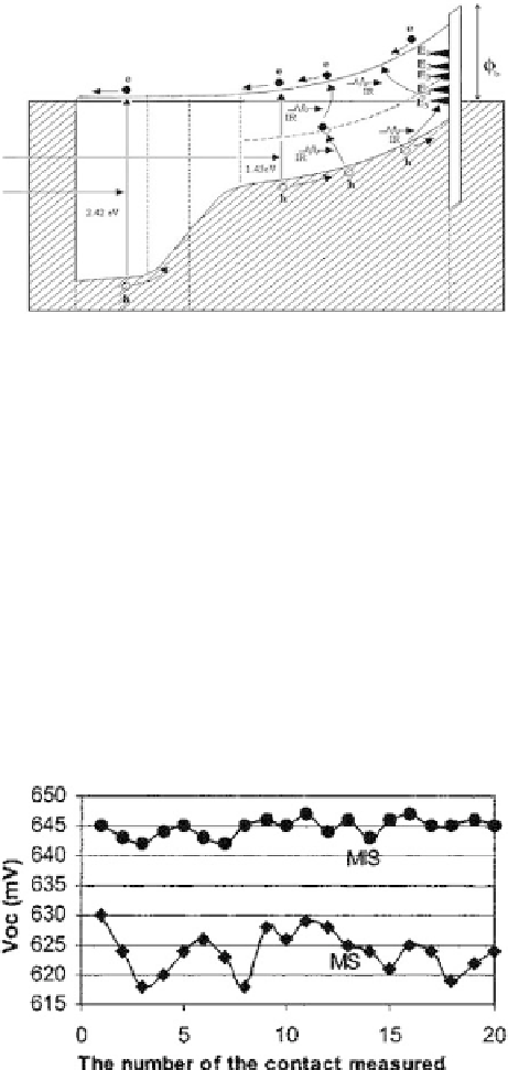
Figure 4.15
An energy band diagram of the glass/CG/CdS/CdTe/
CaF
2
/Au solar cell with an MIS-typeback metal contact [41].
process. To make use of this phenomenon, and to improve
the performance of the CdS/CdTe solar cell, preliminary MIS-
type electrical contact work has been undertaken using vacuum-
evaporated CaF
2
insulating layers [41].
The energy band diagram of such a device showing an improved
φ
b
is shown in Fig. 4.15, and the observed
V
oc
values of MIS
structures are shown in Fig. 4.16 together with those of MS
structures for comparison. The open circuit voltage has increased
foreveryMISstructuremeasured,showingmoreuniform
V
oc
values.
In order to keep the material properties similar, the MS and MIS
Figure 4.16
Open circuit voltage values measured for glass/CG/CdS/
CdTe/Au solar cells with MS- and MIS-typeback metal contacts [41].