Image Processing Reference
In-Depth Information
z
x
FIGURE 10.7
A cosine can be expressed as the sum of two complex phasors rotating in
opposite directions.
At some later time t, the material point initially at
X
has moved to
x
, where
x
u
. Let
X
(
x
) denote a reference map giving the material point position
X
as a function of deformed position
x
. Ignoring T1 effects, the longitudinal
magnetization at time t is
=
X
+
M
(( )
(exp(
Xx
0
M
()
x
=
j
kXx
⋅
( ))
+
exp(
−
j
kXx
⋅
( )
))
(10.12)
z
e
e
2
Thus, the phase of each of the complex phasors encodes the original position
X
.
The HARP technique applies a bandpass filter centered on one of the harmonic peaks
in k-space created by the cosine modulation (Figure 10.8). The filter is designed to
pass frequency and phase components associated with the harmonic peak, and remove
all signal from the other harmonics. The FT of this filtered signal is called the harmonic
image. The phase of this complex image, expressed as an angle in the range [
),
is called the harmonic phase. This phase can be thought of as being fixed with respect
to material coordinates; as the heart deforms, the harmonic phase of a material point
is constant.
−π
,
π
(a)
(b)
(c)
(d)
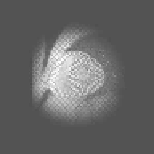
FIGURE 10.8
(a) SPAMM-tagged image at ES. (b) F T showing k-space peaks. (c) Filter
to isolate one peak in k-space. (d) Phase of the HARP image, masked to the LV.


Search WWH ::

Custom Search