Graphics Programs Reference
In-Depth Information
3.
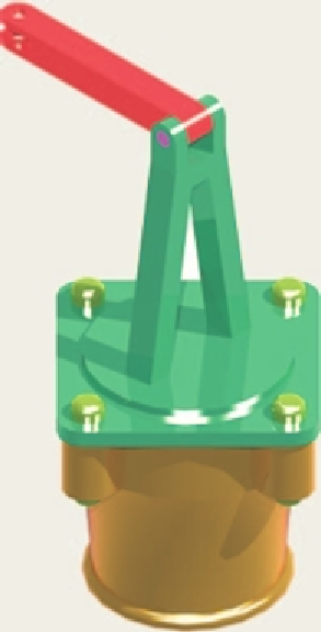
Construct the 3D model shown in the rendering (Fig. 18.24) from the details given in the parts drawing
( Fig. 18.25 ).
135
20
10
R10
Holes Ø10
ARM
1
0
Ø2
0
10
M15
BOLTS
5
10
50
15
Ø120
200
R15
Holes Ø15
UPRIGHT
R5
Ø110
R15
R95
R105
BASE
Tapped M15
Fig. 18.24
Exercise 3
Fig. 18.25
Exercise 3 - the parts drawing
4.
A more dii cult exercise.
A rendered 3D model of the parts of an assembly is
shown in Fig. 18.26.
R20
12.5
R105
Hole Ø50
R115
5
5
Holes Ø10
Ø70
SQ 150
Ø110
Fig. 18.26
Exercise 4 - fi rst orthographic projection


Search WWH ::

Custom Search