Graphics Programs Reference
In-Depth Information
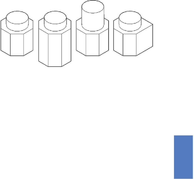
Fourth example - Of set faces ( Fig. 18.7 )
1.
Construct the 3D solid drawing shown in the left-hand drawing of
Fig. 18.7 from a hexagonal extrusion and a cylinder which have been
united using the
Union
tool.
Original model
Upper Face
Offset
Side Face
Offset
Bottom Face
Offset
Fig. 18.7
Fourth example - Offset faces tool
2.
Click
on the
Offset faces
tool icon in the
Home/Solid Editing
panel
(Fig. 18.1). The command line shows:
Command:_solidedit
[prompts]:_face
[prompts]
[prompts]:_offset
Select faces or [Undo/Remove]: pick the bottom
face of the 3D model 2 faces found.
Select faces or [Undo/Remove/All]: enter r right-
click
Select faces or [Undo/Remove/All]: pick
highlighted faces other than the bottom face 2
faces found, 1 removed
Select faces or [Undo/Remove/All]: right-click
Specify the offset distance: enter 30 right-click
3.
Repeat, offsetting the upper face of the cylinder by
50
and the right-
hand face of the lower extrusion by
15
.
The results are shown in Fig. 18.9.
Search WWH ::

Custom Search