Graphics Programs Reference
In-Depth Information
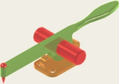
Fig. 17.39
Exercise 4 - a rendering
5.
A rendering of a 3D model drawing of the connecting device shown in the orthographic projection
(Fig. 17.40) is given in Fig. 17.41. Construct the 3D model drawing of the device and add a suitable
lighting to the scene.
Then place in the
ViewCube/Isometric
view, add a material to the model and render.
R2.35"
Ø3.55"
Ø2.95"
R1.55"
Ø0.60
R0.59"
Fig. 17.41
Exercise 5 - a rendering
0.59"
0.20"
R0.20"
0.30"
Fig. 17.40
Exercise 5 - two-view drawing
6.
A fork connector and its rod are shown in a two-view projection (Fig. 17.42). Construct a 3D model
drawing of the connector with its rod in position. Then add lighting to the scene, place in the
ViewCube/Isometric
viewing position, add materials to the model and render.


Search WWH ::

Custom Search