Graphics Programs Reference
In-Depth Information
3.
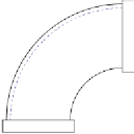
The two-view projection (Fig. 17.37) shows a ducting pipe. Construct a 3D model drawing of the pipe.
Place in an
SW Isometric
view, add lighting to the scene and a material to the model and render.
R1.75"
Ø3.15"
Holes Ø0.0
8
R0.60"
R5.70"
0.60"
0.60"
Fig. 17.37
Exercise 3 - details of shape and sizes
4.
A point marking device is shown in two two-view projections (Fig. 17.38). The device is composed of three
parts - a base, an arm and a pin. Construct a 3D model of the assembled device and add appropriate
materials to each part. Then add lighting to the scene and render in an
SW Isometric
view ( Fig. 17.39 ).
180
20
R7.5
Ø10
R18
0
Pin
Lever
35
3
R3
15
R10
Hole Ø50
45
R45
490
Holes Ø20
R20
R15
R20
Base
10
150
Fig. 17.38
Exercise 4 - details of shapes and sizes


Search WWH ::

Custom Search