Graphics Programs Reference
In-Depth Information
160
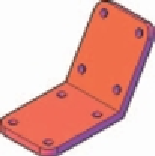
Fig. 17.5
First example - Changing UCS planes - pline for extrusion
6.
At the command line:
Command: enter ucs right-click
Current ucs name: *WORLD*
Specify origin of UCS or [Face/NAmed/OBject/
Previous/View/World/X/Y/Z/ZAxis] <World>:
enter f (Face) right-click
Select face of solid object: pick the sloping
face - its outline highlights
Enter an option [Next/Xfl ip/Yfl ip] <accept>:
right-click
Regenerating model.
Command:
And the 3D model changes its plane so that the sloping face is now on
the new UCS plane.
Zoom
to
1
.
7.
On this new UCS, construct four cylinders of radius 7.5 and height − 15
(note the minus) and subtract them from the face.
8.
Enter
ucs
at the command line again and
right-click
to place the model
in the
*WORLD* UCS
.
9.
Place four cylinders of the same radius and height into position in the
base of the model and subtract them from the model.
10.
Place the 3D model in a
ViewCube/Isometric
view and set in the
Home/View/Conceptual
visual style ( Fig. 17.6 ).
Fig. 17.6
First
example - Changing
UCS planes
Second example - UCS ( Fig. 17.9 )
The 3D model for this example is a steam venting valve - a two-view third
angle projection of the valve is shown in Fig. 17.7.
1.
Make sure that
UCSFOLLOW
is set to
1
.
2.
Place in the
UCS *WORLD
*
view. Construct the
120
square plate at
the base of the central portion of the valve. Construct fi ve cylinders for
the holes in the plate. Subtract the fi ve cylinders from the base plate.


Search WWH ::

Custom Search