Graphics Programs Reference
In-Depth Information
X
and
Y
axes are showing, but when the drawing area is in a 3D view all
three coordinate arrows are showing, except when the model is in the
XY
plane. The icon can be turned off as follows:
Command: enter ucsicon right-click
Enter an option [ON/OFF/All/Noorigin/ORigin/
Properties] <ON>:
To turn the icon off,
enter
off
in response to the prompt line and the icon
disappears from the screen.
The appearance of the icon can be changed by
entering
p
(Properties) in
response to the prompt line. The
UCS Icon
dialog appears in which changes
can be made to the shape, line width and colour of the icon if wished.
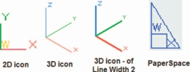
Types of UCS icon
The shape of the icon can be varied partly when changes are made in the
UCS Icon
dialog but also according to whether the AutoCAD drawing
area is in 2D, 3D or Paper Space (Fig. 17.4).
Fig. 17.4
Types of UCS icon
Examples of changing planes using the UCS
First example - changing UCS planes ( Fig. 17.6 )
1.
Set
UCSFOLLOW
to
1
(ON).
2.
Make a new layer colour
Red
and make the layer current. Place the
screen in
ViewCube/Front
and
Zoom
to
1
.
3.
Construct the pline outline (Fig. 17.5) and extrude to
120
high.
4.
Place in
ViewCube/Isometric
view and
Zoom
to
1
.
5.
With the
Fillet
tool, fi llet corners to a radius of
20
.


Search WWH ::

Custom Search