Graphics Programs Reference
In-Depth Information
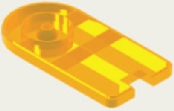
2.
Fig. 15.54 is a rendering of a drip tray. Working to the sizes given in Fig. 15.55, construct a 3D model
drawing of the tray. Add lighting and a suitable material, place the model in an isometric view and
render.
-
"
1
8
1
"
R1-
"
1
2
R-
"
5
8
R-
"
5
8
R2-
"
3
8
-
"
1
8
R-
"
3
4
Fig. 15.54
Exercise 2
8-
"
1
2
Fig. 15.55
Exercise 2 - two-view projection
3.
A three-view drawing of a hanging spindle bearing in third angle orthographic projection is shown
in Fig. 15.56. Working to the dimensions in the drawing construct a 3D model drawing of the bearing.
Add lighting and a material and render the model.
R20
R15
Holes Ø2
0
Ø12
0
Ø10
0
R20
95
Ø120
Ø100
25
240
R5
70
20
Semi-torus Ø1
0
120
50
R40
Hole Ø60
Fig. 15.56
Exercise 3


Search WWH ::

Custom Search