Graphics Programs Reference
In-Depth Information
4.
Render the model (Fig. 15.28) using the
Render Region
tool from the
Render/Render
panel and if now satisfi ed save to a suitable fi le name
( Fig. 15.29 ).
20
5
R45
R40
60
70
20
15
10
R50
15
Holes Ø8
Ø80
R15
Holes Ø10
Fig. 15.29
Second
example - Rendering
5
10
15
100
170
1
5
165
Fig. 15.28
Second example - Rendering - orthographic projection
N o t e
The limited descriptions of rendering given in these pages do not
show the full value of different types of lights, materials and rendering
methods. The reader is advised to experiment with the facilities
available for rendering.
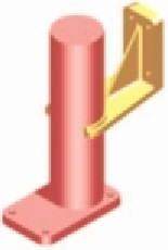
Second example - Rendering a 3D model ( Fig. 15.29 )
1.
Construct 3D models of the two parts of the stand and support
given in the projections (Fig. 15.28) with the two parts assembled
together.
2.
Place the scene in the
ViewCube/Top
view,
Zoom
to
1
and add
lighting.
3.
Add different materials to the parts of the assembly and render the
result.
Fig. 15.28 shows the resulting rendering.


Search WWH ::

Custom Search