Graphics Programs Reference
In-Depth Information
of which were rotated in a
Right
view and
then moved into their position relative to the
other links. Working to suitable sizes construct
a link and from the link construct the chain as
shown.
Fig. 13.19
Exercise 4
an opposite facing model. In the
Isometric
viewport call the
Hide
tool ( Fig. 13.21 ).
Fig. 13.17
Exercise 3
Dimensions in millimetres
23
11
Keyway 9X9
4.
A two-view orthographic projection of a
rotatable lever from a machine is given in
Fig. 13.18 together with an isometric drawing
of the 3D model constructed to the details
given in the drawing Fig. 13.19.
Hole Ø40
R4
Ø60
Ø105
Ø150
5.
Construct the 3D model drawing in a
Four:
Equal
viewport setting.
Holes SQ 9
Ø180
M.Y.Name
Scale 1:1
27/05/2008
FACE PLATE 7/FC
R0.40''
0.40''
Fig. 13.20
Exercise 5 - dimensions
0.40''
3.30''
1'-1.95''
R2.00
''
Ø2.40'
'
R0.30''
0.80''
Fig. 13.18
Exercise 4 - orthographic projection
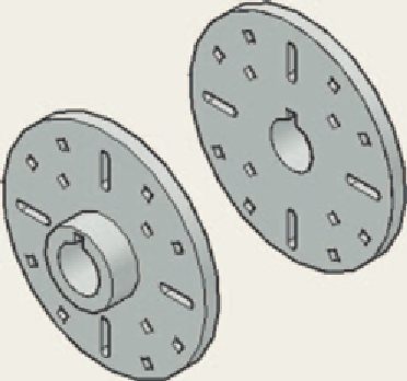
6.
Working in a
Three: Left
viewport setting,
construct a 3D model of the faceplate to
the dimensions given in Fig. 13.20. With
the
Mirror
tool, mirror the model to obtain
Fig. 13.21
Exercise 5


Search WWH ::

Custom Search