Graphics Programs Reference
In-Depth Information
Specify corner or [Cube/Length]: 280,160,10
Specify height or [2Point]: 70
Command:
6.
Place the screen in
3D Navigate/SW Isometric
and
Zoom
to
1
.
7.
Call the
Union
tool from the
Home/Edit
panel and in response to the
prompts in the tool's sequences
pick
each of the 4 objects in turn to
form a union of the 4 objects.
8.
Place in
Visual Styles/Conceptual
.
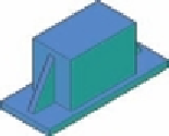
Fig. 12.27
Fourth
example - Box and
Wedge
The result is shown in Fig. 12.27 .
Fifth example - Cylinder and Torus ( Fig. 12.28 )
1.
Make layer
Red
current.
2.
Set
Isolines
to
24
.
3.
Using the
Cylinder
tool from the
Home/Create
panel, construct a
cylinder of centre
180,160
, of radius
40
and height
120
.
4.
Click
the
Torus
tool icon in the
Home/Create
panel. The command
line shows:
Command: _torus
Specify center point or [3P/2P/Ttr]:
180,160,10
Specify radius or [Diameter]: 40
Specify tube radius or [2Point/Diameter]: 10
Command: right-click
TORUS
Specify center point or [3P/2P/Ttr]:
180,160,110
Specify radius or [Diameter] <40>: right-click
Specify tube radius or [2Point/Diameter] <10>:
right-click
Command:
5.
Call the
Cylinder
tool again and construct another cylinder of centre
180, 160
, of radius
35
and height
120
.
6.
Place in the
3D Navigate/SW Isometric
view and
Zoom
to
1
.
7.
Click
the
Union
tool icon in the
Home/Edit
panel and form a union of
the larger cylinder and the two torii.
8.
Click
the
Subtract
tool icon in the
Home/Edit
panel and subtract the
smaller cylinder from the union.
9.
Place in
Visual Styles/X-Ray
.
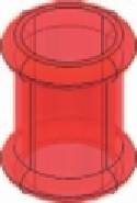
Fig. 12.28
Fifth
example - Cylinder
and Torus
The result is shown in Fig. 12.28 .
Search WWH ::

Custom Search