Graphics Programs Reference
In-Depth Information
Setting the AutoCAD window for isometric drawing
To set the AutoCAD 2011 window for the construction of isometric
drawings:
1.
At the command line:
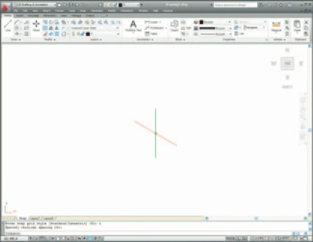
Command: enter snap
Specify snap spacing or [On/Off/Aspect/Rotate/
Style/Type] <5>: s (Style)
Enter snap grid style [Standard/Isometric] <S>:
i (Isometric)
Specify vertical spacing <5>: right-click
Command:
And the grid dots in the window assume an isometric pattern as shown in
Fig. 7.17. Note also the cursor hair lines which are at set in an
Isometric
Left
angle.
Isoplane Top
Fig. 7.17
The AutoCAD grid points set for isometric drawing
I
s
o
p
l
a
n
e
L
e
f
t
I
s
o
p
l
a
n
e
R
ig
h
t
2.
There are three isometric angles -
Isoplane Top
,
Isoplane Left
and
Isoplane Right
. These can be set by pressing either the
F5
function key
or the
Ctrl
and
E
keys. Repeated pressing of either of these 'toggles'
between the three settings. Fig. 7.18 is an isometric view showing the
three isometric planes.
Fig. 7.18
The three
isoplanes


Search WWH ::

Custom Search