Hardware Reference
In-Depth Information
Fig. 6.6
System level structural model
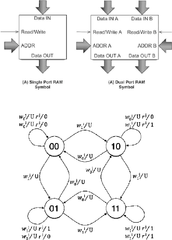
Fig. 6.7
RT-Level behavioral memory model
efficiently model the behavior of faulty memories (
Zarrineh et al.
1998
;
Niggemeyer
et al.
2000
), and to support the automatic generation of memory test algorithms
et al.
(
1992
) proposed in
Benso et al.
(
2008
). It is based on the use of edge labeled
directed graphs, and allows modeling both the internal memory state and the mem-
ory output resulting from read operations. Figure
6.7
shows the model of a memory
composed of 2 one-bit cells identified by i and j , respectively. Nodes represent
memory states while arcs represent transitions among states. Arcs are labeled with
triggering conditions and corresponding memory outputs. Due to the explosion in