Hardware Reference
In-Depth Information
one defect resistance,
O-FC
(f ) is set to 100%. As in the case of
P-FC
, to calculate
G-FC
,
E-FC
and
O-FC
of a fault list, the values for individual faults are averaged.
It is obvious that
P
FC
E
FC
G
FC
O
FC
holds. This means that
E-FC
and
O-FC
can be used as lower and upper bounds of the
exact fault coverage
G-FC
for large circuits for which
G-FC
cannot be computed.
The subsequent sections will provide more details on algorithms for resistive
fault simulation and ATPG. Fault simulation computes fault coverages with respect
to the definitions given above. The main part of a fault simulation procedure is to
obtain C-ADI of a fault. ATPG attempts to find a test pattern for a specific defect or
prove that this defect is redundant. If done consequently, ATPG yields G-ADI as a
by-product and allows the calculation of
G-FC
.
4.2
Interval-Based Fault Simulation
Interval-based fault simulation is the simplest algorithm to determine the resistive
bridging fault (RBF) coverage of a test set. It is based on an electrical analysis and
construction of
analogue detection intervals
(ADIs) at fault site and the propagation
of the ADIs to the outputs of the circuit. C-ADI of a fault is obtained by aggregating
the ADIs at different outputs for all test patterns in a test set. Fault coverage is then
calculated as outlined in the previous section.
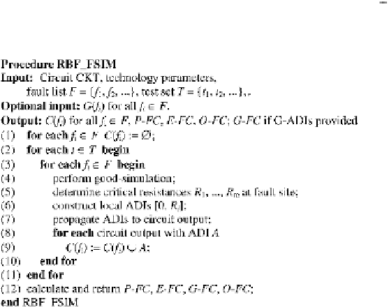
Figure
4.1
shows the pseudo code of the fault simulation procedure
RBF FSIM
.
It takes the circuit and the technology parameters needed for electrical analysis at the
Fig. 4.1
Fault simulation algorithm for resistive bridging faults