Geology Reference
In-Depth Information
Normal Fault
Reverse Fault
Blind Reverse Fault
B
C
A
Blind thrust fault, pure shear, 60° dip
Reverse fault, pure shear, dip 60°, cuts surface
Normal fault, pure shear, dip 60°, cuts surface
a'
a
a'
a'
a
a
cross-section normal to strike
cross-section normal to strike
cross-section normal to strike
100
100
200
50
0
100
0
-100
0
-50
-200
-100
0
10
20
30
40
0
10
20
30
40
0
10
20
30
40
a
a'
a'
a
a
a'
Distance (km)
Distance (km)
Distance (km)
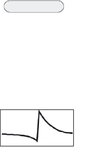
Fig. 11.2
Three-dimensional deformation models of three cases: A. Normal fault, B. Reverse fault, and C. Blind reverse fault.
Dislocations have the same scales and orientations (60
°
dip, same strike) in each model, although the top of the dipping plane is buried in the blind fault
case, C. Each is driven by far-field pure shear stresses, rather than by a prescribed slip on the fault. At the base of each mesh plot is a cross-section of the
vertical displacement field. Note the similarity of the normal and reverse cases, the principal difference being in the asymmetry: in the normal fault case, the
maximum displacement is downward, on the hanging-wall block; whereas in the reverse case, it is upward, again on the hanging-wall block. Note that the
vertical exaggeration is more than 100-fold.